Point of Contact: Dr. Phillip Ligrani, email: phillip.ligrani@uah.edu
Laboratory capabilities include measurements of phenomena related to turbomachines, as well as aerospace engine components with test section inlet Mach numbers from 0.2 up to 3.0. Three parallel test sections provide means to investigate transonic and supersonic flow phenomena, either with or without heat transfer. The high-speed flows are provided using an elaborate air pressure tank supply system with specially provisioned flow and pressure control regulating valves. One currently employed research test section (image below) is designed to operate at an inlet Mach number of 1.54. This facility provides excellent flow characteristics at supersonic velocities, including uniform inlet flow with low turbulence intensity, and minimal flow disturbances. Unique apparatus are employed to control shock wave structure, orientation, and unsteadiness, including a shock wave holding plate and a downstream choking flap. The photograph below shows a resulting normal shock wave with the associated lambda foot, which was obtained using shadowgraph visualization. Unique capabilities include apparatus to investigate SWBLI – Shock Wave Boundary Layer Interactions, shock waves and surface heat transfer on and near gas turbine blade tips, and other aerodynamics and turbomachinery phenomena (as applied either to aero-propulsion, aerodynamic, aerospace, or turbomachinery components) with high-speed, compressible flows at transonic and supersonic Mach numbers. A new transonic test section, containing a linear turbine blade cascade, is under development, which will allow investigation of innovative blade tip configurations, both with and without advanced film cooling arrangements. A test section for teaching laboratory demonstrations of oblique shock waves generated by wedge flows can be found below. Experimental techniques include a variety of devices for measurements of pressure, velocity, temperature, mass flow rates, and heat transfer characteristics, using a variety of devices, including millimeter-scale multiple-hole pressure probes, hot-wire anemometry sensors including subminiature sensors, and infrared thermography. Also available are a variety of flow visualization technologies and apparatus, including Schlieren and shadowgraph systems for visualization of shock wave phenomena. Note that components of these visualization systems are also evident in the image below.
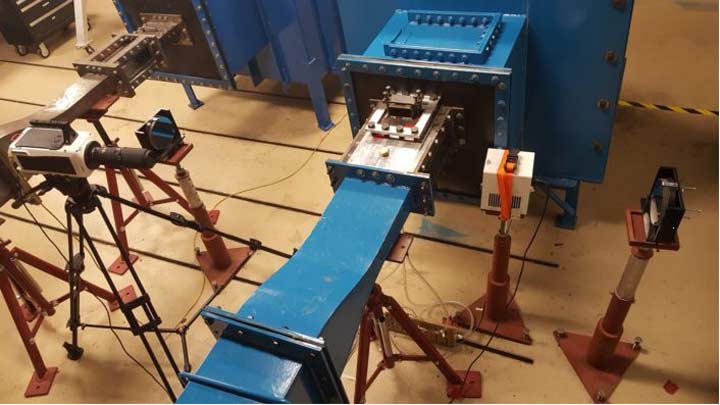
Supersonic Wind Tunnel research test section, teaching demonstration test section, Schlieren and shadowgraph visualization apparatus, and associated components.
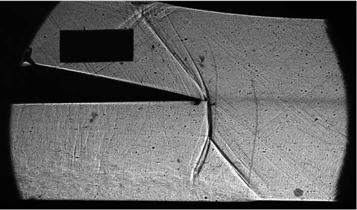
Shadowgraph visualization image from testing on 04-05-2018 of normal shock wave, lambda foot, and resulting separated boundary layer. Flow direction is from right to left, with shock wave holding plate on left side of image, and with rectangular distance reference marker.